
IPhone 7 PLus Schematic Diagrams
All Board, Power management, diagrams of all connectors, Power amplifier, Compass, Pressure sensor, gyroscope, audio,
iPhone 7 Plus_ resistance_ maps Download
iphone 7 PLus A10 CPU .pdf Download
iphone 7 PLus A10 CPU _middle.pdf Download
iphone 7 PLus BB_RF((baseband CPU).pdf Download
iphone 7 PLus BBPMU_RF(baseband power managment).pdf Download
iphone 7 PLus EEPROM_RF .pdf Download
iphone 7 Plus GLNA_RF.pdf Download
iphone 7 Plus GPS.pdf Download
iphone 7 Plus GSMPA_RF (power amplifier).pdf Download
iphone 7 Plus J3001(Big Rear Back camera FPCconnector).pdf Download
iphone 7 Plus J3801 (Fingerprint HOME FPC connector).pdf Download
iphone 7 Plus J4101(lower ribbon flex FPC connecor).pdf Download
iphone 7 Plus J4501 ( rear camera FPC connector).pdf Download
iphone 7 Plus J4502(LCD FPC Cconnector).pdf Download
iphone 7 PLusJ4503 ( front camera MIC3FPC connector ).pdf Download
iphone 7 Plus J4504(power side button FPC connector).pdf Download
iphone 7 Plus LATCP_RF .pdf Download
iphone 7 Plus LBDSM_RF (Power Amplifier).pdf Download
iphone 7 Plus LBLN_RF .pdf Download
iphone 7 Plus LBPA_RF (Power Amplifier) .pdf Download
iphone 7 PLus M2600 .pdf Download
iphone 7 PLus M2800.pdf Download
iphone 7 Plus MBHBPA_RF Power Amplifier.pdf Download
iphone 7 PLus MHBDSM_RF (Power Amplifier).pdf Download
iphone 7 Plus MHBLN_RF .pdf Download
iphone 7 PLus NFBST_RF .pdf Download
iphone 7 PLus NFC_RF .pdf Download
iphone 7 Plus PPLXR_RF.pdf Download
iphone 7 PLus Q2101.pdf Download
iphone 7 Plus QPOET_RF(power amplifier for discharge) .pdf Download
iphone 7 Plus RFBUF_RF .pdf Download
iphone 7 Plus TDDPA_RF (Power Amplifier).pdf Download
iphone 7 Plus U1101 (Logic chip).pdf Download
iphone 7 PLus U2101(Charging IC).pdf Download
iphone 7 Plus U2402 (Compass ).pdf Download
iphone 7 PLus U2403 (Pressure sensing).pdf Download
iphone 7 PLus U2404(Gyroscope) .pdf Download
iphone 7 Plus U3101 (audio).pdf Download
iphone 7 PLus U3301.pdf Download
iphone 7 PLus U3402 .pdf Download
iphone 7 PLus U3502 .pdf Download
iphone 7 PLus U3601 .pdf Download
iphone 7 Plus U3602 .pdf Download
iphone 7 Plus U3603 .pdf Download
iphone 7 PLus U3701( Left backlight boost).pdf Download
iphone 7 Plus U3702 .pdf Download
iphone 7 PLus U3703.pdf Download
iphone 7 PLus U4001 (USB Control).pdf Download
iphone 7 PLus U4601(Right backlight boost) .pdf Download
iphone 7 Plus UATCP_RF .pdf Download
iphone 7 PLus WLAN_RF(WIFI) .pdf Download
iphone 7 Plus XCVR1_RF (Small RF).pdf Download
iphone 7 Plus XCVRO_RF(big RF).pdf Download
iphone 7 Plus_ALL_ BOARD _V1.pdf Download
Step-by-step instructions on how to replace the board in iPhone 7 Plus
In this tutorial, I'll show you how to replace the motherboard for your iPhone 7 Plus yourself. You will need to remove and clean the motherboard if it has been damaged by water.
Before you begin the repair, do not forget to turn off your phone.
To open the iPhone 7 Plus you need a special Pentalobe screwdriver (PL1). Unscrew the two marked screws that are located to the right and left of the power connector (green - 3.3 mm).

Next, you need to detach the display. Place your iPhone 7 Plus on a flat, clean surface to avoid scratching the back of the phone. In order to detach the front panel, you will need a suction cup, hard plastic picks and a regular hair dryer. If your phone screen is badly cracked, cover it with tape before proceeding.
Remember that the screen is well glued to the frame. Using a regular hair dryer, heat the outer edges of the display with warm air (to about 60°). Place the suction cup above or near the Home button. Pull the suction cup up, as if lifting the display from the main part of the phone. Place a plastic pick in the resulting hole between the metal frame and the display. Do not insert the tool deeper than 5 mm to avoid damaging small parts inside the iPhone. Since the display is glued around the entire perimeter of the phone, draw a pick in a circle

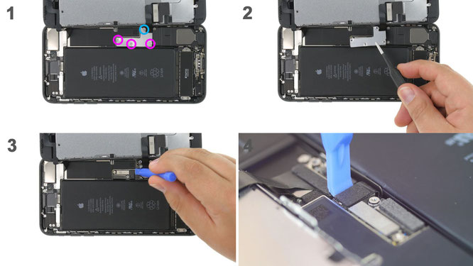
Before starting repairs, disconnect the battery terminal to prevent short circuits and to avoid accidentally turning on the device during repairs.
Unscrew the three marked Y-type screws using a Y-type screwdriver (Y000) and remove the bracket plate (blue - 2.4 mm, pink - 1.1 mm). Now carefully disconnect the battery connector by carefully inserting a plastic spudger underneath it.
Using a plastic spudger to remove the display and home button cables.

Remove the three marked Y-type screws using a Y-type screwdriver (Y000) and remove the cover. Using a plastic spudger, carefully remove the FaceTime front camera connector from the motherboard. You can now remove the display completely.

Remove the two marked screws from the main camera bracket and remove it. Disconnect the main camera connectors by very carefully inserting a plastic spudger under the connectors and unplugging them. The screw marked green (Standoff) is not magnetic. There are special screwdrivers for removing STANDOFF screws, but you can also use a regular, thin screwdriver. Next, use a plastic spatula to detach the main camera unit from the holder and remove the camera unit.

Remove the marked Phillips screw that is screwed into the side of the back cover. Then disconnect the connector from the motherboard. The Wi-Fi antenna is slightly glued. Use warm air to warm it up and remove it by inserting a steel spatula under the cable. Then remove the Wi-Fi antenna.
To begin, remove the marked Phillips screws from the antenna bracket (green - 1.1 mm, blue - 1.0 mm). One of the screws is screwed into the back cover from the side. Then remove the bracket.

There are two more Phillips screws under the antenna bracket that hold the connector in place. Unscrew these screws (green - 1.1 mm). Now remove the connecting piece.
Remove the two marked screws on the bracket plate above the connector on the top of the motherboard (green - 1.1mm). Carefully remove the connector using a plastic spudger. Next, disconnect the wide connector on the side of the motherboard and the two small antenna cable plugs.

Now first remove the SIM card tray. Next, unscrew all the marked screws that hold the motherboard (green - 1.8 mm, blue - 2.0 mm, yellow - 1.1 mm). You can remove internal threaded screws using a special screwdriver or a regular thin slotted screwdriver. Now carefully remove the motherboard. Use a plastic spatula to remove it if necessary. There is a plastic screw holder next to the two holes for the main iSight camera. This plastic holder is located on the top of the motherboard.

Now install the motherboard in its original position. The camera bracket should be on top of the motherboard. Secure the motherboard with screws (green - 1.8 mm, blue - 2.0 mm, yellow - 1.1 mm). Insert the SIM card tray
ihsan ali (Monday, 09 September 2024 17:50)
i am technician
atiepf (Saturday, 20 January 2024 03:02)
good