
FIC Schematics Diagram. Service Manuals

MotherBoard Schematic. Schematic Page Description, PCI & IRQ & DMA Description, Block Diagram, Nat name Description, Board Stack up Description, Schematic modify Item and History, power on & off & S3 Sequence, Layout Guideline, switch setting. PDF Free Download
| FIC AT11 - Schematics Diagrams. Service Manual | Download |
| FIC KR2W_K8_ATI - Schematics Diagrams. Service Manual | Download |
| FIC LM10W - Schematics Diagrams. Service Manual | Download |
| FIC LM7R - Schematics Diagrams. Service Manual | Download |
| FIC LM7W - Schematics Diagrams. Service Manual | Download |
| FIC MR030 - Schematics Diagrams. Service Manual | Download |
| FIC PTB51 - Schematics Diagrams. Service Manual | Download |
| FIC PTT50 - MotherBoard Schematic Service Manual | Download |
If you have diagrams that you are ready to share, send them to [email protected]
If you haven't found what you're looking for, write in the comments below.
FIC AZ11E
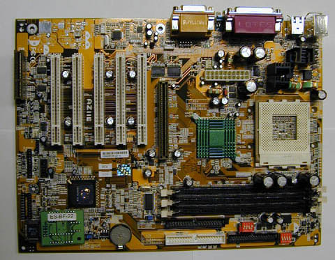
AZ11E Specifications:
Processor: Socket A Athlon or Duron
Chipset:
- North Bridge VIA 8363 (KT133)
- South Bridge VIA 686B
Memory:
- 3 banks of DIMMs
- PC100 and PC133 memory supported
- Maximum capacity: 1.5GB
- Supports asynchronous FSB and memory frequencies
Slots: 1xAGP, 5xPCI, 1xCNR
I/O ports:
- 2xUltraDMA 33/66/100 IDE ports
- 1xFDD, 2xCOM, 1xLPT, PS/2 keyboard and mouse
- 4xUSB (2 on board and 2 optional)
Like most modern motherboards, AZ11E has several features that may be useful to inexperienced users, they are called the NOVUS system.
BIOS Guardian will not allow a virus to damage the board's BIOS. Hotkey - there are two BIOS settings presets (Default and Optimized Settings), one of which can be loaded while the system is booting by pressing Ctrl and P. If you overclocked too much and the system does not boot, then pressing Ins during boot will restore the default settings , FIC calls it Overclock Partner. Clockometer - a utility for overclocking the processor. Audio Alert - a module that can be purchased separately (for about $15) will report problems by voice. ..The MSI K7T Pro2 had something of similar terrible quality... You can draw your own logo (or use any picture) and with the help of Logo Genie it will appear when the system boots.
A few words about the location of the components. The disadvantages of the board include the capacitors located close to the processor socket. The ATX power connector is also poorly located - to the left of the processor socket, because of which the cables will be located above it, and this will impair ventilation inside the system unit. Another drawback is the first DIMM bank, it is located next to the AGP slot, so when installing a new memory module you will have to remove the video card.